1. The type of commutation when the load is commutated by transferring its load current to another incoming thyristor is
a) class A or load commutation
b) class B or resonant commutation
c) class C or complementary commutation
d) class D or impulse commutation
Explanation: In the Class C type commutation also called as complementary commutation the load is commutated by transferring the current th another device.
2. The type of commutation in which the pulse to turn off the SCR is obtained by separate voltage source is
a) class B commutation
b) class C commutation
c) class D commutation
d) class E commutation
Explanation: In class E commutation, another voltage source is used. It is also called as external pulse commutation.
3. The natural reversal of ac supply voltage commutates the SCR in case of
a) forced commutation
b) only line commutation
c) only natural commutation
d) both line & natural commutation
Explanation: Both line and natural commuataion are used in converters.
4.___________ commutation technique is commonly employed in series inverters.
a) line
b) load
c) forced
d) external-pulse
Explanation: Load commuation is used in inverter in which L and C are connected in series with the load or C in parallel with the load such that overall load circuit is under damped.
5. For the circuit shown in the figure below,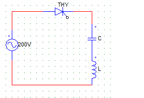
C = 4 pF
L = 16 μH
Vs = 200V
The capacitor voltage after the SCR is self commutated is
a) -100 V
b) -200 V
c) -400 V
d) 0 V
Explanation: It is simply the negative of Vs as it is a series circuit & after turn off the whole voltage appears across the thyristor.
6. For the circuit shown below,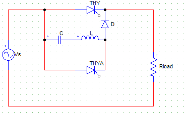
The maximum value of current through thyristors T1 & TA can be given by
a) Vs/R, Vs√C/L
b) Vs √C/L, Vs/R
c) Vs/R + LC, Vs
d) Vs/LC, Vs/R
Explanation: I1 = (Vs/R)
T2 = (Vs√C/L).
7. For the circuit shown in the figure below,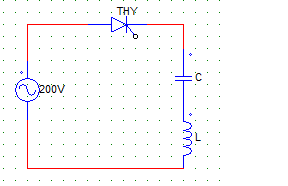
C = 4 pF
L = 16 μH
Vs = 200 V
The peak thyristor current is
a) 800 A
b) 400 A
c) 100 A
d) 50 A
Explanation: The peak SCR current is Vs/2.
8. For the circuit shown in the figure below, ___ type of commutation would take place for the SCR (THY1)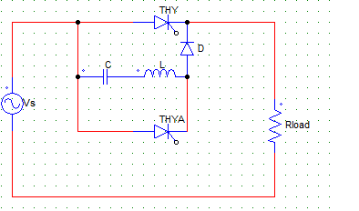
a) line
b) load
c) forced
d) external-pulse
Explanation: The given figure is that of a class B commutation or resonant-pulse commutation, which is a type of forced commutation technique.
9. For the circuit shown in the figure below,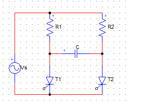
R1 = 50 Ω, R2 = 100 Ω, Vs = 100 V. At the time of turn-on of the SCR, initial thyristor current is
a) 0 A
b) 10 A
c) 5 A
d) 3.5 A
Explanation: Io = Vs x [(2/R1)+(1/R2)].
10. Natural commutation of an SCR takes place when
a) voltage across the device becomes negative
b) voltage across the device becomes positive
c) gate current becomes zero
d) anode current becomes zero
Explanation: Anode current (load current) becomes zero and turns off the device, hence the name line commutation.