1. When the switch is closed, the steady state current through the diode is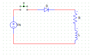
a) Vo/C
b) Vo/R
c) Vo
d) Vo/(RC)
Explanation: I = Vo/R
2. When the switch is open, the current through the diode in the positive cycle is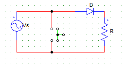
a) zero
b) Vs/R
c) Vs/(R+Rd)
d) none of the mentioned
Explanation: When the switch is open, the diode is forward biased and I = Vs/(Rd + R). Where, Rd is the diode resistance.
3. For the circuit shown in the figure below, consider the diode as an ideal diode & R.M.S value of source voltage as Vs.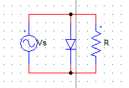
The output voltage waveform at R is most likely to have
a) zero value in the positive half cycle and a peak value of 1.414Vs in the negative half cycle
b) sine-wave nature with a peak value 1.414Vs
c) zero value in the negative half cycle and a peak value of 1.414Vs in the positive half cycle
d) sine-wave nature with a peak value Vs
Explanation: The diode S.C’s the load in the positive half cycle.
4. For the circuit shown in the figure below, V8 is AC voltage source with peak value Vm. The waveform of the load voltage at the resistor is
a) zero in the positive half & peak value of –(Vm) negative half
b) zero in the negative half & peak value of –(Vm-V1) in the positive half
c) zero in the positive half & peak value of –(Vm+V1) negative half
d) zero in the positive half & peak value of –(Vm-V1) negative half
Explanation: Diode is reversed biased in the positive half cycle. In the negative half cycle, apply KVL to get the value of peak voltage at the load.
5. In the process of diode based rectification, the alternating input voltage is converted into
a) an uncontrolled alternating output voltage
b) an uncontrolled direct output voltage
c) a controlled alternating output voltage
d) a controlled direct output voltage
Explanation: Rectification is AC to DC. In DIODE biased rectification, control is not possible.
6. In a half-wave rectifier, the
a) current & voltage both are bi-directional
b) current & voltage both are uni-directional
c) current is always uni-directional but the voltage can be bi-directional or uni-directional
d) current can be bi-directional or uni-directional but the voltage is always uni-directional
Explanation: Current is always in one direction only, but voltage can be bi-directional in case of an L load.
7. For a certain diode based rectifier, the output voltage (average value) is given by the equation
1/2π [ ∫Vm sin ωt d(ωt) ]
Where the integral runs from 0 to π
The rectifier configuration must be that of a
a) single phase full wave with R load
b) single phase full wave with RL load
c) single phase half wave with R load
d) single phase half wave with RL load
Explanation: Integration is 0 to π from base period of 1/2π so it is a half wave R load.
8. For a single phase half wave rectifier, with R load, the diode is reversed biased from ωt =
a) 0 to π, 2π to 2π/3
b) π to 2π, 2π/3 to 3π
c) π to 2π, 2π to 2π/3
d) 0 to π, π to 2π
Explanation: Diode will be reversed biased in the negative half cycles.
9. For the circuit shown below,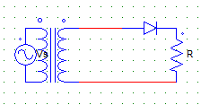
The secondary transformer voltage Vs is given by the expression
Vs = Vm sin ωt
Find the PIV of the diode.
a) √2
b) Vs
c) Vm
d) √2 Vm
Explanation: PIV = √2 Vs = Vm.
10. For the circuit shown below,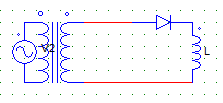
The peak value of the load current occurs at ωt = ?
a) 0
b) π
c) 2π
d) Data is insufficient
Explanation: Due to the L nature, load current is maximum when the diode will be com-mutated i.e at π.