1.Find the rms value of the output voltage for the circuit shown below.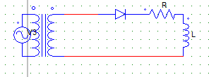
Voltage across the secondary is given by Vm sinωt.
a) Vm
b) 2Vm
c) Vm/2
d) Vm2/2
Explanation: The above is a HW diode rectifier, the RMS o/p voltage equation is given by
Vor = √ [ (1/2π) ∫π Vm2sin2ωt. d(ωt) ] Solving above equation we get, Vor = Vm/2.
2. In a 1-Phase HW diode rectifier with R load, the average value of load current is given by
Take Input (Vs) = Vm sinωt
a) Vm/R
b) Vm/2R
c) Vm/πR
d) Zero
Explanation: Vo = √ [(1/2π) ∫π Vm sinωt. d(ωt)] Vo = Vm/π
I = Vo/R = Vm/πR.
3. In the circuit shown below,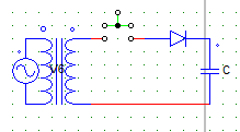
The switch (shown in green) is closed at ωt = 0. The load current or capacitor current has the maximum value at ωt =
a) 0
b) π
c) 2π
d) none of the mentioned
Explanation: The instant switch is closed the load current will be zero due to the nature of the capacitor.
4. Find the average value of output current for a 1-phase HW diode rectifier with R load, having RMS output current = 100A.
a) 200R A
b) 100/R√2 A
c) 200/R√2 A
d) 200/Rπ A
Explanation: I(rms) = Vm/2R
Therfore, Vm = 200R
I(avg) = Vm/πR = 200R/πR.
5. A 1-phase 230V, 1KW heater is connected across a 1-phase HW rectifier (diode based). The power delivered to the heater is
a) 300 W
b) 400 W
c) 500 W
d) 600 W
Explanation: R = (230 x 230)/1000
V(rms) = (√2 x 230)/2
P = V(rms)2/R = 500W.
6. A 1-phase half wave diode rectifier with R load, has input voltage of 240 V. The input power factor is
a) Unity
b) 0.707 lag
c) 0.56 lag
d) 0.865 lag
Explanation: Input p.f = V(rms)/Vs
Vrms is the RMS value of output voltage. Vrms = (√2 x 230)/2
Vs = 230
pf = 0.707.
7. A 1-phase half wave diode rectifier with R = 1 KΩ, has input voltage of 240 V. The diode peak current is
a) Zero
b) 240mA
c) 24mA
d) 0.24mA
Explanation:Diode peak current = peak current through the load = Vo/R = Vm/2R.
8. For the below given circuit, after the switch is closed the voltage across the load (shown open) remains constant.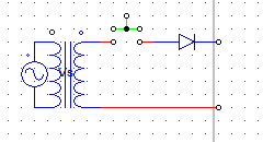
Assuming that all initial conditions are zero. The element across the load would be a/an
a) resistor
b) capacitor
c) inductor
d) data not sufficient
Explanation: As the voltage remains constant as soon as the switch is closed, the element is most likely to be a capacitor.
9. For the below given circuit,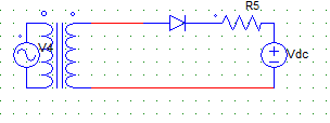
After the supply voltage (Vs) is given the
a) diode starts conducting
b) diode starts conducting only when Vs exceeds Vdc
c) diode never conducts
d) diode stops conducting only when Vs exceeds Vdc
Explanation: The diode will be forward biased only when Vs will be greater than Vdc.
10. For the below given circuit,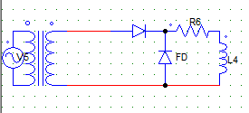
With Vs = Vm sin ωt (secondary side). The expression for the average voltage is
a) Vm
b) Vm/2π
c) Vm/π
d) Vm/2
Explanation: Due to the FD, we get 1st quadrant operation.
Where, output voltage (Avg) = 1/2π [ ∫Vm sin ωt d(ωt) ], integration runs from 0 to 180 degrees