1.The gate-cathode curve for an SCR is given by the relation Vg = (1+10)Ig. The gate voltage source is a rectangular pulse of peak value 15 V and current = 0.659 A. Find the source resistance.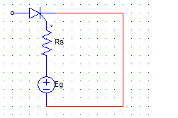
a) 90.2 Ω
b) 11.24 Ω
c) 46.2 Ω
d) 39 Ω
Explanation: Es = Rs.Ig + Vg
Vg = 1+10 Ig
Therefore Rs = (15-1)/0.659.
2. Find the triggering frequency when the average gate power dissipation = 0.3 W and the peak gate drive power is 5 Watts. The gate source has a pulse width of 20 μsec duration.
a) 3 kHz
b) 0.3 kHz
c) 30 kHz
d) 0.03 mHz
Explanation: (Pgm) = (Pgav)/Duty Cycle
Duty Cycle = f x T = (Pgav)/(Pgm)
Duty Cycle = 0.3/5
T = 20 μsec.
0.3/5 = f x T
f = (0.3)/(5 x 20 x 10-6) = 3000 Hz.
3. The duty cycle can be written as
a) f x T
b) f/T
c) T/f
d) f
Explanation: The duty cycle is defined as the ratio of pulse-on period to periodic time of pulse.
The pulse on period is T, and the periodic time is 1/f.
It is to be noted that T = pulse width whereas f = (1/T1) = frequency of firing or pulse repetition rate
4. The major function of the pulse transformer is to
a) increase the voltage amplitude
b) reduce harmonics
c) isolate low & high power circuit
d) create periodic pulses
Explanation: Isolation of the two circuit is done by the transformer, as the transformer is a magnetically coupled device and any mishap at the load side will not damage the other side of the circuitry.
5. In a resistance firing circuit the firing angle
a) cannot be greater than 120°
b) cannot be greater than 90°
c) cannot be greater than 180°
d) cannot be greater than 160°
Explanation: The R firing circuits cannot be used for alpha greater than 90 degrees.
6. For a R firing circuit, the maximum value of source voltage is 100 V. Find the resistance to be inserted to limit the gate current to 2 A.
a) 5 Ω
b) 50 Ω
c) 500 Ω
d) 0.5 Ω
Explanation: R = 100/2 = 50 Ohm.
7. The diode in the R firing circuit
a) ensures that the gate voltage is a half wave DC pulse
b) ensures that the gate voltage is a full wave DC pulse
c) ensures that the gate voltage is a half wave AC pulse
d) ensures that the gate voltage is a full wave AC pulse
Explanation: The diode is placed between the resistances and gate which ensures that the current flows in one direction only.
8. In case of an RC half wave triggering circuit, the firing angle can be ideally varied between
a) 0 to 180
b) 0 to 90
c) 0 to 120
d) 0 to 360
Explanation: Unlike the R firing circuit, the RC firing circuits can be used to obtain firing angle greater than 180. Although practically 0 and 180 degree is improbable.
9. In the figure given below, the resistance R1 is used to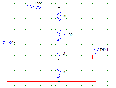
a) keep the gate circuit voltage drop minimum
b) limit the gate current to a safe value when R2 = 0
c) limit the gate current to a safe value when R2 is very large
d) allow the gate power dissipation
Explanation:As R2 is the variable, R1 makes sure that the current does not exceed the maximum value when R2 is kept at zero position.
10. In case of a R firing with R2 as the variable resistance, Vgp (peak of gate voltage) and Vgt (gate triggering voltage) the value of R2 is so adjusted such that
a) Vgp = Vgt
b) Vgp > Vgt
c) Vgp < Vgt
d) Vgp = Vgt = 0
Explanation: For turning on the device, the peak of gate voltage must be equal to the gate triggering voltage.