1. Examine the below shown circuit.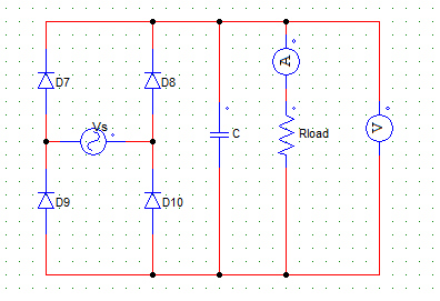
While D7 & D10 are reversed biased the
a) capacitor is charging through Vs
b) capacitor is discharging through Vs
c) capacitor is charging through R
d) capacitor is discharging through R
Explanation: When the two are reversed biased and the other two SCR’s are not yet gated, the stored energy in the capacitor is supply the load R.
2. When a certain type of filter is connected across the R load of a full wave bridge type diode biased rectifier, the following output voltage waveform is obtained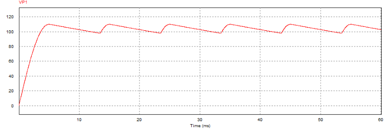
The filter connected is most likely to be a/an
a) L filter
b) C filter
c) LC filter
d) None of the above mentioned
Explanation: It is to be noted that the waveform is that of a voltage parameter. The voltage goes up for a very small time and than goes down (discharges) for longer time. For every half wave the peak of the waveform is to the left, if it were to be on the right it would be more likely to be a L filter.
3. For the below given circuit,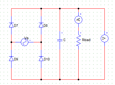
When the output current rises, the capacitor current
a) is increasing
b) is decreasing
c) is constant
d) is zero
Explanation: When the load current is increasing, the capacitor is charging through the source voltage & its current keeps on falling & voltage rises.
4. A single-phase diode B-2 rectifier is fed from a 250 V, 50 Hz source & connected to a load of R = 400 Ω.
Design a capacitor filter such that the ripple factor of the output voltage is less than 5 %. Find the value of the capacitance of the C filter.
a) 156.4 μF
b) 500 μF
c) 189 μF
d) 246 μF
Explanation: Use,
C = K * [1 + 1/√2RF] Where, K = 1/4fR.
5. In a single pulse semi-converter using two SCRs, the triggering circuit must produce
a) two firing pulses in each half cycle
b) one firing pulse in each half cycle
c) three firing pulses in each cycle
d) one firing pulse in each cycle
Explanation: A single phase semi-converter has only two SCRs & two diodes. Hence, only two pulses are required in each cycle, one in each half.
6. In a 3-phase full converter using six SCRs, gating circuit must provide
a) one firing pulse every 30°
b) one firing pulse every 90°
c) one firing pulse every 60°
d) three firing pulses per cycle
Explanation: 60° x 6(devices) = 360°.
7. In the complete firing circuit, the driver circuit consists of
a) pulse generator & power supply
b) gate leads & power supply
c) pulse amplifier & pulse transformer
d) pulse detector & pulse amplifier
Explanation: The driver circuit consists of a pulse amplifier to increase the magnitude of the gate pulse to a sufficient value. The pulse transformer then provides pulses to individual SCRs.
8. Find the average gate power dissipation (Pgav) when the maximum allowable gate power dissipation (Pgm) = 10 kW, with a duty cycle = 50 %.
a) 10 KW
b) 5 KW
c) 2.5 KW
d) 7 KW
Explanation: (Pgm) = (Pgav)/Duty Cycle.
9. The magnitude of gate voltage and gate current for triggering an SCR is
a) inversely proportional to the temperature
b) directly proportional to the temperature
c) inversely proportional to the anode current requirement
d) directly proportional to the anode current requirement
Explanation: Higher the temperature lesser will be the gate current required as the temperature must have already excited some of the atoms
10. Find the amplitude of the gate current pulse, when the gate-cathode curve is given by the relation Vg = [(1+10) x Ig]
The peak gate drive power is 5 Watts.
a) 359mA
b) 659mA
c) 1.359 A
d) 1.659 A
Explanation:
(1+10 Ig).Ig = 5 Watts
Ig = 0.59 A.