1. . If a C.E. stage has a load Rl and transconductance gm, what is the factor by which the capacitance between the base and the collector at the output side gets multiplied?
a) 1 + 1/gmRl
b) 1 – 1/gmRl
c) 1 + 2/gmRl
d) 1 – 2/gmRl
Explanation: The low frequency response of the C.E. stage is gmRl. By the application of miller effect, we find that the capacitance between the base and the collector, looking from the output side, will be increased by a factor of 1 + 1/gmRl. Hence, the correct option is 1 + 1/gmRl.
2. If a C.E. stage with early effect has a load Rl and transconductance gm, what is the factor by which the capacitance between the base and the collector at the output side, gets multiplied?
a) 1 + 2/gm*(Rl || ro)
b) 1 – 1/gm*(Rl || ro)
c) 1 + 1/gm*(Rl || ro)
d) 1 – 2/gm*(Rl || ro)
Explanation: If the early effect is considered, the low frequency response of the C.E. stage becomes gm*(Rl || ro). Thereby, miller approximation shows that the capacitance between the base and the collector, looking from the output side, will be increased by a factor of 1 + 1/gm*(Rl || ro). Hence the correct option is 1 + 1/ gm*(Rl || ro).
3. For a high frequency response of a simple C.E. stage with a transconductance of gm, what is Cin?
a) Cµ(1 + gm*R2) – Cπ
b) Cµ(1 + gm*R2) + Cπ
c) Cµ(1 – 2*gm*R2) + Cπ
d) Cµ(1 + 2*gm*R2) – Cπ
Explanation: The input capacitance is an equivalent of the base to emitter capacitance in parallel to the miller approximation of the base to collector capacitance. Due to miller approximation, the base to collector capacitance becomes Cµ(1+gm*R2) while the base to emitter capacitance is Cπ. Capacitors get added, when in parallel and thus Cµ(1+gm*R2) + Cπ is correct.
4. For a high frequency response of a simple C.E. stage with a transconductance of gm, what is Cout?
a) Ccs – Cµ*(2 + 1/gm*R2)
b) Ccs + Cµ*(1 + 2/gm*R2)
c) Ccs – Cµ*(1 + 1/gm*R2)
d) Ccs + Cµ*(1 + 1/gm*R2)
Explanation: We have a capacitor from the collector to substrate, Ccs, which comes in parallel to the miller approximation of the capacitance from base to collector. The miller approximation defines the latter as Cµ*(1 + 1/gm*R2). Since capacitors gets added, when in parallel, the correct option is Ccs + Cµ*(1+ 1/gm*R2).
5. In Miller’s theorem, what is the constant K?
a) Total voltage gain
b) Internal voltage gain
c) Internal current gain
d) Internal power gain
Explanation: The constant K=V2/V1, which is the internal voltage gain of the network.
Thus resistance RM=R/1-K
RN=R/1-K-1.
6. When applying miller’s theorem to resistors, resistance R1 is for node 1 and R2 for node 2. If R1>R2, then for same circuit, then for capacitance for which the theorem is applied, which will be larger, C1 or C2?
a) C1
b) C2
c) Both are equal
d) Insufficient data
Explanation: Given R1>R2
R/1-K > R/1-K-1, and so 1-K-1>1-K
Thus K2>1, K>1, K<-1 (correct)
Thus, C1=C(1-K) and C2=C(1-K-1)
Hence C1>C2.
7. Find net voltage gain, given hfe = 50 and hie = 1kΩ.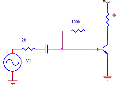
a) 27.68
b) -22
c) 30.55
d) -27.68
Explanation: Apply millers theorem to resistance between input and output.
At input, RM=100k/1-K = RI
Output, RN=100k/1-K-1 ≈ 100k
Internal voltage gain , K = -hfeRL’/hie
K = – 50xRc||100k/1k = – 50x4x100/104 = – 192
RI = 100k/1+192 = 0.51kΩ
RI’ = RI||hie = 0.51k||1k = 0.51×1/1.51 = 0.337kΩ
Net voltage gain = K.RI’/RS+RI’ = – 192 x 0.337/2k + 0.337k = -27.68
8. Given that capacitance w.r.t the input node is 2pF and output node is 4pF, find capacitance between input and output node.
a) 0.67 pF
b) 1.34pF
c) 0.44pF
d) 2.2pF
Explanation: C1=C(1-K), C2=C(1-K-1)
C1=2pF
C2=4pF
C1/C2=1/2=1-K/1-K-1
K = -2
C1 = C(1+2) = 3C
C = C1/3 = 2/3pF = 0.67 pF.
9. Consider an RC coupled amplifier at low frequency. Internal voltage gain is -120. Find the voltage gain magnitude, when given that collector resistance = 1kΩ, load = 9kΩ, collector capacitance is 0. is 0.1μF, and input frequency is 20Hz.
a) 120
b) 12
c) 15
d) -12
Explanation: AV = -120
fL = 1/2πCC(RC+RL) = 1/2π*0.001 = 1000/2π = 159.15Hz
AV’ = \(\frac{|AV|}{\sqrt{1}} + (\frac{f_L}{f})^2\)
AV’ = 120/8.02 ≈ 15.
10. Find the 3-dB frequency given that the gain of RC coupled amplifier is 150, the low frequency voltage gain is 100 and the input frequency is 50Hz.
a) 50.8 Hz
b) 55.9 Hz
c) 60Hz
d) 100Hz
Explanation: AVM = 150
AVL = 100
f = 50Hz
100 = \(\frac{150}{\sqrt{1}}+(\frac{f_L}{50})^2\)
1+f2/2500 = 1.52
f2 = 2500*1.25 = 3125
f = 55.90 Hz.