1. In the given circuit, what is the current through the parallel resistor?
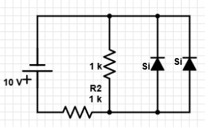
a) 9.3 mA
b) 0.7 mA
c) 8.6 mA
d) 0 mA
Explanation: As the resistor is in parallel with the diodes, the voltage that appears across it is 0.7 V. Hence, current = 0.7 mA.
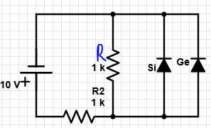
2. In the given circuit, what is the value of current through R?
a) 0.7 mA
b) 0.3 mA
c) 1 mA
d) 10 mA
Explanation: The source voltage initially increases from 0-10 V. As the source voltage increases, the voltage across the diodes also increases. When the voltage across the diodes reaches a value of 0.3 V, the Germanium diode starts conducting, whereas the silicon diode is still in the off state. Hence, the voltage across R = 0.3 V. Hence, current = 0.3 mA.
3. In the given circuit, what is the value of current through R2?
a) 9.3 mA
b) 9.7 mA
c) 10 mA
d) 0 mA
Explanation: Here, the voltage across R=0.3 V, hence, current through R2 = (10-0.3) V/ 1 k = 9.7 mA.
4. In the given circuit, what is the value of current through the silicon diode?
a) 9.3 mA
b) 9.7 mA
c) 10 mA
d) 0 mA
Explanation: The source voltage initially increases from 0-10 V. As the source voltage increases, the voltage across the diodes also increases. When the voltage across the diodes reaches a value of 0.3 V, the Germanium diode starts conducting, whereas the silicon diode is still in the off state. Hence, the voltage across silicon diode = 0.3 V and hence, the current according to the approximate equivalent circuit model is equal to zero.
5. In the given circuit, what is the value of current through the germanium diode?
a) 9.4 mA
b) 9.7 mA
c) 0.3 mA
d) 0 mA
Explanation: Current through R2 = 9.7 mA. Also, current through R = 0.3 mA, current through the silicon diode = 0 mA. Hence, from the KCL, we get the current through the germanium diode to be 9.4 mA.
6. In the given circuit, by what amount does the current across R change when the Germanium diode is reconnected in the reverse-bias mode?
a) 0 mA
b) 0.7 mA
c) 0.4 mA
d) 0.3 mA
Explanation: When the germanium diode is forward biased, current through R = 0.3 mA. When the Germanium diode is reverse biased, current through R = 0.7 mA. Hence, change in current = 0.4 mA.
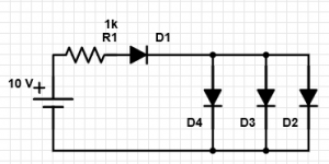
7. In the given circuit, if the diode D2 is a Germanium diode and all other diodes are Silicon diodes, then which of the following statements is true?
a) ID2 < ID3; ID2 = ID1
b) ID2 > ID3; ID2 > ID1
c) ID2 > ID3; ID2 = ID1
d) ID2 > ID3; ID2 < ID1
Explanation: Voltage across the parallel diodes = 0.3 V. Hence, current through D3 = 0. Hence ID2 > ID3. Also, as both the parallel silicon diodes are in parallel and in off-state, the diodes 1 and 2 are in series and hence, current through them is same.
8. In the circuit, considering the diode 1,4 to be a Germanium diode and the diodes 2,3 to be silicon, which of the following statements are true?
a) ID1 = ID2
b) ID1 = ID3
c) ID1 = ID4
d) ID1 > ID4
Explanation: In the given circuit, the silicon diodes are in off-state as the voltage across them is 0.3 V. Hence, they act as open circuit and the diodes 1 and 4 are in series and hence the current through diodes 1 and 4 is same.
9. Which of the following equipment can’t be used to check the condition of a diode?
a) Digital Display Meter
b) Ohmmeter
c) Curve Tracer
d) CRO
Explanation: All the methods may be used to test a diode for its proper functioning except CRO.
10. What is the expected reading obtained on a Digital Display Meter with diode-checking function when a proper functioning silicon semiconductor diode is connected across its leads in the forward bias configuration?
a) 0.67 V
b) 0.3 V
c) Open Loop Indication
d) Varies with the diode
Explanation: The diode checking function on the meter when used causes a current of 2 mA to flow through the diode and hence under forward bias, the voltage is determined to be 0.67 V. Germanium diodes show a drop around 0.3V.