1. Which of the following models of a semiconductor diode is the most widely used for the purpose of calculation?
a) Approximate Equivalent Model
b) Ideal Diode Model
c) Piecewise Linear Model
d) Hybrid model
Explanation: Approximate Equivalent model not only saves time and efforts but also provides results with a considerable amount of accuracy.
2. Which of the following statement holds true?
Statement-1: Piecewise linear model is generally not used for diode analysis.
Statement-2: The value of Rav is negligible as compared to the load resistance.
a) Statement-1 is true, Statement-2 is true and Statement-2 is a proper explanation for Statement-1
b) Statement-1 is true, Statement-2 is true and Statement-2 is not a proper explanation for Statement-1
c) Statement-1 is true, Statement-2 is false
d) Statement-1 is false, Statement-2 is true
Explanation: Piecewise linear model involves a line with a slope equal to 1/Rav. As Rav is low, 1/ Rav is high and the slope becomes almost equal to infinity and hence, it approaches the equivalent circuit model and hence, the piecewise linear model isn’t generally used.
3. From the given circuit diagram, considering the diode to be a silicon semiconductor diode, what is the magnitude of diode current? (Use an appropriate model of the diode)
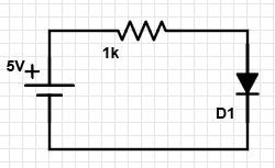
a) 43 mA
b) 0 mA
c) 4.3 mA
d) 5 mA
Explanation: ID = (V-VD)/R = 4.3 mA.
4. From the given circuit diagram, what is the value of diode current?
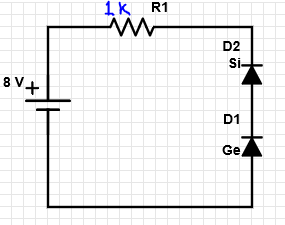
a) 8 mA
b) 7.3 mA
c) 0 mA
d) 7 mA
Explanation: As both the diodes are reverse biased, the current in the circuit is zero.
5. From the given circuit diagram, what is the value of diode current?
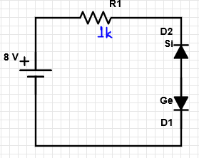
a) 8 mA
b) 0 mA
c) 7.3 mA
d) 7 mA
Explanation: As the silicon diode in the circuit is reverse biased, hence the current in the circuit is zero.
6. From the given circuit diagram, what is the value of diode current? Use an appropriate diode model.
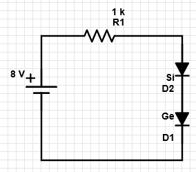
a) 8 mA
b) 0 mA
c) 7.3 mA
d) 7 mA
Explanation: The diodes have a drop of 0.3V for Ge and 0.7V for Silicon in forward bias. We can use the constant voltage model, and hence in forward bias, the current flowing is
ID = (V-VD1-VD2)/R = 7 mA.
7. From the given circuit diagram, what is the value of diode current?
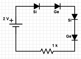
a) 2 mA
b) 0 mA
c) 1.3 mA
d) 1 mA
Explanation:The diodes in forward bias, have drops of 0.3V for Ge and 0.7V for Si, and the total drops cancel out the source voltage, and hence the diode current is zero.
8. From the given circuit diagram, what is the value of voltage across the resistor?

a) 2 V
b) 1.3 V
c) 1 V
d) 0 V
Explanation: The diodes in forward bias, have drops of 0.3V for Ge and 0.7V for Si, and the total drops cancel out the source voltage, and hence the diode current is zero. Hence voltage drop is also zero.
9. From the given circuit diagram, what is the value of diode current?

a) 2.425 mA
b) 5.2 mA
c) 2.325 mA
d) 0 mA
Explanation: Here, ID=(V-VD)/R = 2.325 mA.
10. From the given circuit diagram, what is the value of voltage across R2?
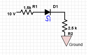
a) 9.324 V
b) 5.3 V
c) 0 V
d) 5.8125 V
Explanation: Here, current I=10-0.7/4k=2.325 mA
Here, VR2 = I x R2 = 5.8125 V.