1. From the given circuit diagram, what is the voltage across diode?
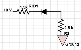
a) 10 V
b) 5 V
c) 0.7 V
d) 0 V
Explanation: As the diode is reverse biased, the current in the circuit is zero and hence the voltage across the diode is equal to the source voltage = 10 V.
2. From the given circuit diagram, what is the value of diode current?

a) 2.425 mA
b) 5.2 mA
c) 2.325 mA
d) 0 mA
Explanation: As the diode is reverse biased, the current in the circuit is zero.
3. What is the circuit in the given diagram called?

a) Clipper
b) Clamper
c) Half wave rectifier
d) Full wave rectifier
Explanation: The circuit given above is a clipper. The diode conducts when it is forward biased, i.e, whenever the input vi is greater than 5V (for ideal diode). For lower voltages, the diode does not conduct and the output is zero.
4. What is the circuit in the given diagram called?
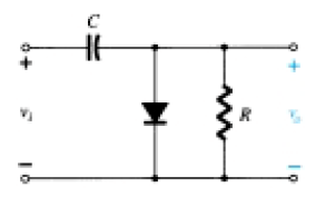
a) Clipper
b) Clamper
c) Half wave rectifier
d) Full wave rectifier
Explanation: During the positive half cycle, the diode is forward biased and no signal appears across the output. The capacitor holds the charge in that state. During negative cycle, diode is reverse biased and diode does not conduct. The charge in capacitor is released and is obtained at the output.
5. For a sinusoidal input of 20 Vpeak to the given circuit, what is the peak value of the output waveform?
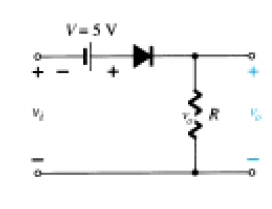
a) 20 V
b) 25 V
c) 0 V
d) -25 V
Explanation: In the given circuit, the output becomes zero for vi less than -5 V. Hence, the peak value of the output is 25 V owing to the additive effect of V for vi.
6. For the given circuit for a 20 Vpeak sinusoidal input vi, what is the value of vi at which the clipping begins?

a) 5 V
b) 0 V
c) -5 V
d) Clipping doesn’t occur
Explanation: Considering the connection of diode, it is evident that the diode becomes reverse biased when vi < -5 V. Hence, clipping starts at -5 V.
7. For a sinusoidal input of 20 Vpeak to the given circuit, what is the minimum value of the output waveform?
a) 20 V
b) 25 V
c) -25 V
d) 0 V
Explanation: The given circuit is a clipper that cuts off a part of the negative cycle of the input sinusoid i.e. the output becomes zero for a certain region of the input waveform. Hence, the minimum value is 0 V.
8. For the given input waveform to the given circuit, what is the peak value of the output waveform?
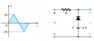
a) 0 V
b) 16 V
c) 12 V
d) 0 V
Explanation: In the given circuit, the diode is in the off stage when vi > 4 V. Hence, when vi > 4 V, vo = vi and hence the peak value of vo = the peak value of vi = 16 V.
9. For the given input waveform to the given circuit, what is the minimum value of the output waveform?
a) 4 V
b) 16 V
c) 12 V
d) 0 V
Explanation:The circuit above is a parallel clipper. When the input is less than 4V, then diode is forward biased and thus output voltage is 4V. When input increases above 4V, the diode is reverse biased and output is equal to the input. Hence, minimum output is 4V.
10. Which of the following is not a necessary component in a clamper circuit?
a) Diode
b) Capacitor
c) Resistor
d) Independent DC Supply
Explanation: Diode, Capacitor and Resistor are necessary to build a clamper circuit. An independent DC supply is required to bring an additional shift.