1. Zener diodes can be effectively used in voltage regulator. However, they are these days being replaced by more efficient
a) Operational Amplifier
b) MOSFET
c) Integrated Circuits
d) None of the mentioned
Explanation: ICs have been widely adapted by the industries over conventional zener diodes as their better replacements for a voltage regulators.
2. . A 9.1-V zener diode exhibits its nominal voltage at a test current of 28 mA. At this current the incremental resistance is specified as 5 Ω. Find VZ0 of the Zener model.
a) 8.96V
b) 9.03V
c) 9.17V
d) 9.24V
Explanation: VZ = VZo + MZ IZT
9.1 = VZo + 5 * 28 * 10-3
VZo = 8.96v
VZ = VZo + 5IZ = 8.96 * 5IZ.
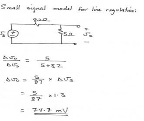
3. A shunt regulator utilizing a zener diode with an incremental resistance of 5 Ω is fed through an 82-Ω resistor. If the raw supply changes by 1.0 V, what is the corresponding change in the regulated output voltage?
a) 72.7 mV
b) 73.7 mV
c) 74.7 mV
d) 75.7 mV
Explanation:
4. A designer requires a shunt regulator of approximately 20 V. Two kinds of Zener diodes are available: 6.8-V devices with rz of 10 Ω and 5.1-V devices with rz of 30 Ω. For the two major choices possible, find the load regulation. In this calculation neglect the effect of the regulator resistance R.
a) -30mV/mA and 120mV/mA respectively
b) 30mV/mA and 60mV/mA respectively
c) -60mV/mA and +60mV/mA respectively
d) -30mV/mA and -120mV/mA respectively
Explanation: Three 6.8v zeners provide 3*6.8 = 20.4v with 3 * 10 =30Ω Resistance, neglecting R, we have
load Regulation = -30mV/mA.
For 5.1 Zeners we need 4 diodes to provide 20.4v with 4 * 30 =120Ω Resistance.
load Regulation = -120mV/mA .
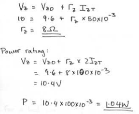
5. Partial specifications of a Zener diode is provided. VZ = 10.0 V, VZK = 9.6 V, and IZT = 50 mA. Assuming that the power rating of a breakdown diode is established at about twice the specified Zener current (IZT), what is the power rating of each of the diodes described above?
a) 1.04 W
b) 0.104 W
c) 10.4 mW
d) 1.04 mW
Explanation:
6.Which of the following isn’t a type of rectifier?
a) Precision Half-wave Rectifier
b) Bridge Rectifier
c) Peak Rectifier
d) None of the mentioned
Explanation:All of the mentioned are different types of a rectifier
7.For a half wave or full wave rectifier the Peak Inverse Voltage of the rectifier is always
a) Greater than the input voltage
b) Smaller than the input voltage
c) Equal to the input voltage
d) Greater than the input voltage for full wave rectifier and smaller for the half wave rectifier
Explanation: The peak input voltage is smaller than the input voltage due to the presence of diode(s). A single diode reduces the output voltage by approximately 0.7V
8. For a half-wave rectifier having diode voltage VD and supply input of VI, the diode conducts for π – 2Θ, where Θ is given by
a) tan -1 VD/VI
b) tan-1 VD/VI – VI
c) sin-1 VD/VI
d) sin-1 VD/VI – VI
Explanation: The diode doesn’t conducts when VD ≥VI . Hence Θ = sin-1 (D/VI).
9. Bridge rectifier is an alternative for
a) Full wave rectifier
b) Peak rectifier
c) Half wave rectifier
d) None of the mentioned
Explanation: Bridge rectifier is a better alternative for a full wave rectifier.
10. Which of the following is true for a bridge rectifier?
a) The peak inverse voltage or PIV for the bridge rectifier is lower when compared to an identical center tapped rectifier
b) The output voltage for the center tapped rectifier is lower than the identical bridge rectifier
c) A transistor of higher number of coil is required for center tapped rectifier than the identical bridge rectifier
d) All of the mentioned
Explanation: All of the given statements are true for a bridge rectifier.