1. A circuit is given in the figure below. The Thevenin equivalent as viewed from terminals x and x’ is ___________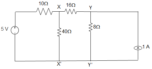
a) 8 V and 6 Ω
b) 5 V and 6 Ω
c) 5 V and 32 Ω
d) 8 V and 32 Ω
Explanation: We, Thevenized the left side of xx’ and source transformed right side of yy’.

Vxx’ = Vth = \(\displaystyle\frac{\frac{4}{8} + \frac{8}{24}}{\frac{1}{8} + \frac{1}{24}}\) = 5V
∴ Rth = 8 || (16 + 8)
= \(\frac{8×24}{8+24}\) = 6 Ω
2. For the circuit given in figure below, the Thevenin equivalent as viewed from terminals y and y’ is _________
a) 8 V and 32 Ω
b) 4 V and 32 Ω
c) 5 V and 6 Ω
d) 7 V and 6 Ω
Explanation: We, Thevenized the left side of xx’ and source transformed right side of yy’.
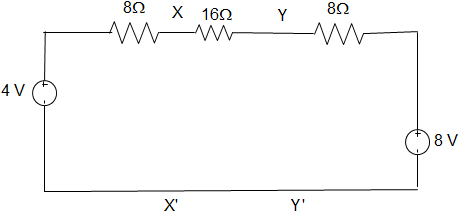
Thevenin equivalent as seen from terminal yy’ is
Vxx’ = Vth = \(\displaystyle\frac{\frac{4}{24} + \frac{8}{8}}{\frac{1}{24} + \frac{1}{8}}\) = 5V
= \(\frac{0.167+1}{0.04167+0.125}\) = 7 V
∴ Rth = (8 + 16) || 8
= \(\frac{24×8}{24+8}\) = 6 Ω.
3. In the following circuit, when R = 0 Ω, the current IR equals to 10 A. The value of R, for which maximum power is absorbed by it is ___________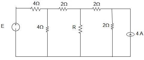
a) 4 Ω
b) 3 Ω
c) 2 Ω
d) 1 Ω
Explanation: The Thevenin equivalent of the circuit is as shown below.
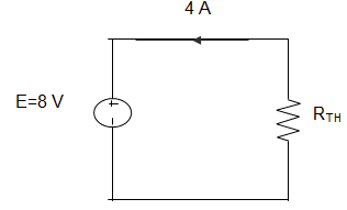
Therefore from the figure we can infer that Rth = 2 Ω
4. In the following circuit, when R = 0 Ω, the current IR equals to 10 A. The maximum power will be?
a) 50 W
b) 100 W
c) 200 W
d) 400 W
Explanation: The Thevenin equivalent of the circuit is as shown below.
I = 10 A, Rth = 2 Ω
∴ Pmax = (\(\frac{10}{2}\))2 × 2
= 5×5×2 = 50 W.
5. For the circuit given below, the Thevenin resistance across the terminals A and B is _____________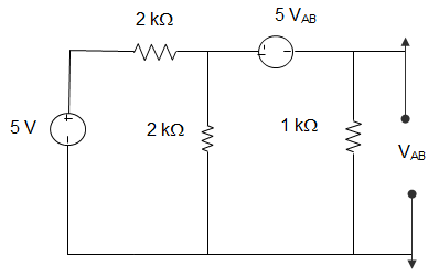
a) 5 Ω
b) 7 kΩ
c) 1.5 kΩ
d) 1.1 kΩ
Explanation: Let VAB = 1 V
5 VAB = 5
Or, 1 = 1 × I1 or, I1 = 1
Also, 1 = -5 + 1(I – I1)
∴ I = 7
Hence, R = 0.2 kΩ.
6. For the circuit given below, the Thevenin voltage across the terminals A and B is ____________
a) 1.25 V
b) 0.25 V
c) 1 V
d) 0.5 V
Explanation: Current through 1 Ω = \(\frac{5}{2}\) – I1
Using source transformation to 5 V sources, VOC = 1 × I1
VOC = -5 VOC + (\(\frac{5}{2}\) – I1) × 1
Eliminating I1, we get, VOC = 0.5 V.
7. In the following circuit, the value of open circuit voltage and the Thevenin resistance between terminals a and b are ___________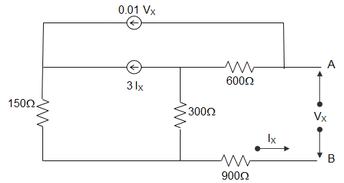
a) VOC = 100 V, RTH = 1800 Ω
b) VOC = 0 V, RTH = 270 Ω
c) VOC = 100 V, RTH = 90 Ω
d) VOC = 0 V, RTH = 90 Ω
Explanation: By writing loop equations for the circuit, we get,
VS = VX, IS = IX
VS = 600(I1 – I2) + 300(I1 – I2) + 900 I1
= (600+300+900) I1 – 600I2 – 300I3
= 1800I1 – 600I2 – 300I3
I1 = IS, I2 = 0.3 VS
I3 = 3IS + 0.2VS
VS = 1800IS – 600(0.01VS) – 300(3IS + 0.01VS)
= 1800IS – 6VS – 900IS – 3VS
10VS = 900IS
For Thevenin equivalent, VS = RTH IS + VOC
So, Thevenin voltage VOC = 0
Resistance RTH = 90Ω.
8. In the circuit given below, it is given that VAB = 4 V for RL = 10 kΩ and VAB = 1 V for RL = 2kΩ. The values of the Thevenin resistance and voltage for the network N are ____________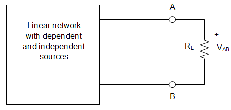
a) 16 kΩ and 30 V
b) 30 kΩ and 16 V
c) 3 kΩ and 6 V
d) 50 kΩ and 30 V
Explanation: When RL = 10 kΩ and VAB = 4 V
Current in the circuit I = \(\frac{V_{AB}}{R_L} = \frac{4}{10}\) = 0.4 mA
Thevenin voltage is given by VTH = I (RTH + RL)
= 0.4(RTH + 10)
= 0.4RTH + 4
Similarly, for RL = 2 kΩ and VAB = 1 V
So, I = \(\frac{1}{2}\) = 0.5 mA
VTH = 0.5(RTH + 2)
= 0.5 RTH + 1
∴ 0.1RTH = 3
Or, RTH = 30 kΩ
And VTH = 12 + 4 = 16 V.
9. For the circuit shown in figure below, the value of the Thevenin resistance is _________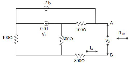
a) 100 Ω
b) 136.4 Ω
c) 200 Ω
d) 272.8 Ω
Explanation: IX = 1 A, VX = Vtest
Vtest = 100(1-2IX) + 300(1-2IX – 0.01VS) + 800
Vtest = 1200 – 800IX – 3Vtest
4Vtest = 1200 – 800 = 400
Vtest = 100V
RTH = \(\frac{V_{test}}{1}\) = 100 Ω.
10. For the circuit shown in the figure below, the Thevenin voltage and resistance looking into X-Y are __________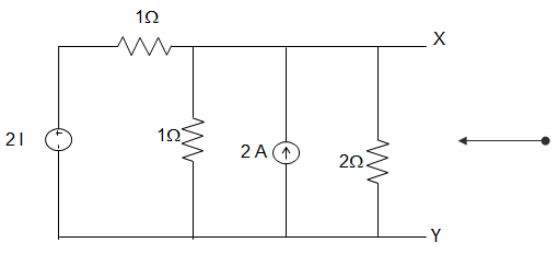
a) \(\frac{4}{3}\) V and 2 Ω
b) 4V and \(\frac{2}{3}\) Ω
c) \(\frac{4}{3}\) V and \(\frac{2}{3}\) Ω
d) 4 V and 2 Ω
Explanation: \(R_{TH} = \frac{V_{OC}}{I_{SC}}\)
VTH = VOC
Applying KCL at node A, \(\frac{2I-V_{TH}}{1} + 2 = I + \frac{V_{TH}}{2}\)
Or, I = \(\frac{V_{TH}}{1}\)
Putting, 2VTH – VTH + 2 = VTH + \(\frac{V_{TH}}{2}\)
Or, VTH = 4 V.
RTH = 4/2 = 2Ω