1. One multiplexer can take the place of ___________
a) Several SSI logic gates
b) Combinational logic circuits
c) Several Ex-NOR gates
d) Several SSI logic gates or combinational logic circuits
Explanation: A multiplexer (or MUX) is a device that selects one of several analog or digital input signals and forwards the selected input into a single line, depending on the active select lines. Since many operational behaviour can be performed by using a multiplexer. Whereas, a combinational circuit is a combination of many logic gates which makes the circuit more complex
2. A digital multiplexer is a combinational circuit that selects ___________
a) One digital information from several sources and transmits the selected one
b) Many digital information and convert them into one
c) Many decimal inputs and transmits the selected information
d) Many decimal outputs and accepts the selected information
Explanation: A digital multiplexer is a combinational circuit that selects one digital information from several sources and transmits the selected information on a single output line depending on the status of the select lines. That is why it is also known as a data selector
3. In a multiplexer, the selection of a particular input line is controlled by ___________
a) Data controller
b) Selected lines
c) Logic gates
d) Both data controller and selected lines
Explanation: The selection of a particular input line is controlled by a set of selected lines in a multiplexer, which helps to select a particular input from several sources
4. If the number of n selected input lines is equal to 2^m then it requires _____ select lines.
a) 2
b) m
c) n
d) 2n
Explanation: If the number of n selected input lines is equal to 2^m then it requires m select lines to select one of m select lines
5. How many select lines would be required for an 8-line-to-1-line multiplexer?
a) 2
b) 4
c) 8
d) 3
Explanation: 2n input lines, n control lines and 1 output line available for MUX. Here, 8 input lines mean 23 inputs. So, 3 control lines are possible. Depending on the status of the select lines, the input is selected and fed to the output.
6. A basic multiplexer principle can be demonstrated through the use of a ___________
a) Single-pole relay
b) DPDT switch
c) Rotary switch
d) Linear stepper
Explanation: A basic multiplexer principle can be demonstrated through the use of a rotary switch. Since its behaviour is similar to the multiplexer. There are around 10 digits out of which one is selected one at a time and fed to the output
7. How many NOT gates are required for the construction of a 4-to-1 multiplexer?
a) 3
b) 4
c) 2
d) 5
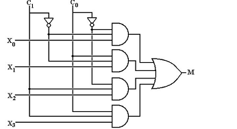
Explanation: There are two NOT gates required for the construction of 4-to-1 multiplexer. x0, x1, x2 and x3 are the inputs and C1 and C0 are the select lines and M is the output.
The diagram of a 4-to-1 multiplexer is shown below:
8. The enable input is also known as ___________
a) Select input
b) Decoded input
c) Strobe
d) Sink
Explanation: The enable input is also known as strobe which is used to cascade two or more multiplexer ICs to construct a multiplexer with a larger number of inputs. Enable input activates the multiplexer to operate
9. 4 to 1 MUX would have ____________
a) 2 inputs
b) 3 inputs
c) 4 inputs
d) 5 inputs
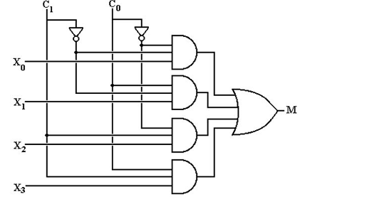
Explanation: 4 to 1 multiplexer would have 4 inputs (X0, X1, X2, X3), 2 select lines (C1, C0) and 1 output (M). It can be observed from this diagram:
10. The two input MUX would have ____________
a) 1 select line
b) 2 select lines
c) 4 select lines
d) 3 select lines
Explanation: The two input multiplexer would have n select lines in 2n. Thus n =1. Therefore, it has 1 select line.