1. The output sum of two decimal digits can be represented in ____________
a) Gray Code
b) Excess-3
c) BCD
d) Hexadecimal
Explanation: The output sum of two decimal digits can be represented in BCD(Binary-coded decimal). Binary-coded decimal (BCD) is a class of binary encodings of decimal numbers where each decimal digit is represented by a fixed number of bits, usually four or eight
2.The addition of two decimal digits in BCD can be done through ____________
a) BCD adder
b) Full adder
c) Ripple carry adder
d) Carry look ahead
Explanation: The addition of two decimal digits in BCD can be done through BCD adder. Every input inserted, in addition by the user converted into binary and then proceed for the addition. Whereas, Full Adder, Ripple Carry Adder and Carry Look Adder are for the addition of binary bits.
3. 3 bits full adder contains ____________
a) 3 combinational inputs
b) 4 combinational inputs
c) 6 combinational inputs
d) 8 combinational inputs
Explanation: 3 bits full adder contains 23 = 8 combinational inputs
4. The simplified expression of full adder carry is ____________
a) c = xy+xz+yz
b) c = xy+xz
c) c = xy+yz
d) c = x+y+z
Explanation: A full adder is a combinational circuit having 3 inputs and 2 outputs, namely SUM and CARRY. The simplified expression of full adder carry is c = xy+xz+yz
5. Complement of F’ gives back __________
a) F’
b) F
c) FF
d) FF’
Explanation: Complement means inversion. So, complement of F’ gives back F, as per the Law of Involution.
6. Decimal digit in BCD can be represented by ____________
a) 1 input line
b) 2 input lines
c) 3 input lines
d) 4 input lines
Explanation: Binary-coded decimal (BCD) is a class of binary encodings of decimal numbers where each decimal digit is represented by a fixed number of bits, usually four or eight. Decimal digit in BCD can be represented by 4 input lines. Since it is constructed with 4-bits.
7. The number of logic gates and the way of their interconnections can be classified as ____________
a) Logical network
b) System network
c) Circuit network
d) Gate network
Explanation: The number of different levels of logic gates is represented in a fashion which is known as a logical network.
8.Which of the following logic expressions represents the logic diagram shown?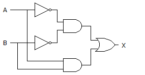
a) X=AB’+A’B
b) X=(AB)’+AB
c) X=(AB)’+A’B’
d) X=A’B’+AB
Explanation: 1st output of AND gate is = A’B’
2nd AND gate’s output is = AB and,
OR gate’s output is = (A’B’)+(AB) = AB + A’B’.
9. The device shown here is most likely a ________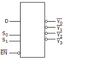
a) Comparator
b) Multiplexer
c) Inverter
d) Demultiplexer
Explanation: The given diagram is demultiplexer, because it takes single input & gives many outputs. A demultiplexer is a combinational circuit that takes a single output and latches it to multiple outputs depending on the select lines.
10. What type of logic circuit is represented by the figure shown below?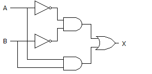
a) XOR
b) XNOR
c) AND
d) XAND
Explanation: After solving the circuit we get (A’B’)+AB as output, which is XNOR operation. Thus, it will produce 1 when inputs are even number of 1s or all 0s, and produce 0 when input is odd number of 1s.