1. After earthing, the different parts of an electrical machinery are at _________
a) infinite potential
b) intermediate potential
c) zero potential
d) undefined potential
Explanation: After earthing, the various parts of electrical machinery such as casing, armoring of cables, etc are at zero potential
2. Connection of the various parts of a circuit to earth has a _________
a) medium resistance
b) high resistance
c) very high resistance
d) very low resistance
Explanation: Once an electrical apparatus is grounded, most of its components are at ground potential. When the different parts of electrical machinery are connected to the ground, they possess very low resistance
3. Specific resistance of soil is _________
a) changes from soil to soil
b) is constant
c) depends on the circuit connected to it
d) depends on the supply voltage
Explanation: Specific resistance depends on the nature and properties of a material. Specific resistance is different for various types of soils such as dry soil, rocky soil, wet soil, etc.
4. Circuit shows the method of Measurement of low resistance by Ammeter-Voltmeter method. The measured resistance Rm for the given Circuit is _________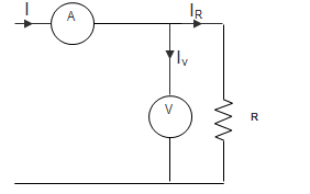
a) Rx + Rv
b) \(\frac{R_x^2}{R_x + R_v}\)
c) \(\frac{R_v^2}{R_x + R_v}\)
d) \(\frac{R_x R_v}{R_x + R_v}\)
Explanation: Measured resistance Rm = \(\frac{V_x}{I_A} = \frac{V_x}{I_v + I_R}\)
\(\frac{I_v}{V_x} = \frac{1}{R_v}\) And \(\frac{I_R}{V_x} = \frac{1}{R_X}\)
So, Rm = \(\frac{R_x R_v}{R_x+R_v}\)
5. Circuit shows the method of Measurement of low resistance by Ammeter-Voltmeter method. What is the percentage error?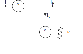
a) Zero
b) \(\frac{R_x}{R_x + R_v}\) × 100
c) \(– \frac{R_x}{R_x + R_v}\) × 100
d) \(– \frac{R_v}{R_x + R_v}\) × 100
Explanation: Percentage Error = \(\frac{R_m – R_x}{R_x}\) × 100
\(= \frac{R_x R_v – R_x(R_x-R_v)}{R_x (R_x+R_v)}\) × 100
∴ Percentage Error = \(– \frac{R_x}{R_x + R_v}\) × 100.
6. The readings of polar type potentiometer are I = 12.4∠27.5°, V = 31.5∠38.4°. Then, reactance of the coil will be ________
a) 2.51 Ω
b) 2.56 Ω
c) 2.54 Ω
d) 2.59 Ω
Explanation:Here, V = 31.5∠38.4°
I = 12.4∠27.5°
Z = \(\frac{31.5∠38.4°}{12.4∠27.5°}\) = 2.54∠10.9°
But Z = R + jX = 2.49 + j0.48
∴ Reactance X= 2.54 Ω.
7. The voltage drop across a standard resistor of 0.2 Ω is balanced at 83 cm. Find the magnitude of the current, if the standard cell emf of 1.53 V is balanced at 42 m.
a) 13.04 A
b) 10 A
c) 14.95 A
d) 12.56 A
Explanation: Voltage drop per unit length = \(\frac{1.53}{42}\) = 0.036 V/cm
Voltage drop across 83 cm length = 0.036 × 83 = 2.99 V
∴ Current through resistor, I = \(\frac{2.99}{0.2}\) = 14.95 A.
8. A resistance R is measured using the connection shown in the below figure.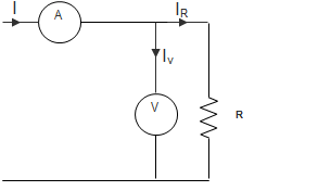
The current measured is 10 A on ranges 100A and the voltage measured is 125 V on 150 V range. The scales of the ammeter and voltmeter are uniform. The total number of scale divisions of the ammeter is 100 and that of the voltmeter is 150. The scale division can be distinguished. The constructional error of the ammeter is ± 0.3% and that of voltmeter±0.4%. The resistance of the ammeter is 0.25 Ω.
The value of R is?
a) 12.75 Ω
b) 12.0 Ω
c) 12.25 Ω
d) 12.5 Ω
Explanation: Percentage error in ammeter = \(± \frac{1}{10×100} × 100\) = ± 0.1%
Percentage error in voltmeter= \(± \frac{1}{10×150} × 100\) = ± 0.067%
So, δI = ± 0.3 ± 0.1 = ± 0.4%
δV = ± 0.4 ± 0.067 = ± 0.467%
R = \(\frac{V}{I}\)
So, error = ± δV ± δI = ± 0.867
Measured value of resistance = \(R_m = \frac{125}{10}\) = 12.5
∴ True value = \(R_m(1-\frac{Ra}{R_m})\) = 12.25 Ω.
9. A resistance R is measured using the connection shown in the below figure.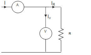
The current measured is 10 A on ranges 100A and the voltage measured is 125 V on 150 V range. The scales of the ammeter and voltmeter are uniform. The total number of scale divisions of the ammeter is 100 and that of the voltmeter is 150. The scale division can be distinguished. The constructional error of the ammeter is ± 0.3% and that of voltmeter±0.4%. The resistance of the ammeter is 0.25 Ω.
The possible error in the measurement of R is?
a) ±0.11 Ω
b) ±0.15 Ω
c) ±0.867 Ω
d) ±0.625 Ω
Explanation: Possible error is ± 0.867, so,
12.25 ± 0.867%
Or, 12.25 ± 0.11 Ω.
10. Low resistance is measured by ___________
a) De-Sauty’s bridge
b) Maxwell’s bridge
c) Kelvin double bridge
d) Wein’s bridge
Explanation: De-Sauty’s bridge is used for measurement of Capacitance; Maxwell’s bridge is used for measurement of Inductance and Wein Bridge for Frequency. Kelvin double bridge is used for measurement of Low resistance